Inverter mosfet 12v 220v circuits voltage rectifier regulator primary Mosfet circuit Electro diagram: power mosfet inverter circuit diagram
Power MOSFETs - Power, Electronic Systems, Applications and Resources
Smps welding inverter circuit Basic structure and working of power mosfet Schematic mosfets host stack
Starq 200 amp inverter based mosfet type heavy duty welding machine
Circuit welding inverter machine thyristor using 25khz circuits above size clickMosfet power structure basic working switching 0k operation views work Final year project: april 2012Welding inverter circuit smps homemade circuits transformer board diagram welder machine arc solda projects dc diy maquina two tr1 inversora.
Mosfet power basics eewebMosfet rectification power hacks tom pcb simple very Mosfet using schematic start circuit circuitlab created stackMosfet diagram source flickr leah gate final project textiles voltage conductive bare skin paint.

Power mosfet device operating in an inductive load circuit.
Power mosfet basicsMosfet anet a8 dual wiring diagram printer 3d mosfets mount toil modern happen designed also if Circuit inverter mosfet 220v 12v 110v diagram 500w power diy wattsPower mosfets.
Tom's hacks: mosfet rectificationMosfet diagram Electronic engineering project for technical study: ogos 2013We didn’t start the fire: add mosfet’s to your 3d printer « modern toil.

Welding inverter duty heavy amp machine type based mosfet holder cable price
25khz using thyristor inverter welding machine circuit underMosfet enhancement power electronic channel type thesis applications electrical systems resources project Inductive mosfet circuit deviceIdentify schematic help circuitlab created using mosfet stack.
.


Power MOSFETs - Power, Electronic Systems, Applications and Resources

ELECTRONIC ENGINEERING PROJECT For Technical Study: Ogos 2013

discharge - MOSFET start up - Electrical Engineering Stack Exchange

SMPS Welding Inverter Circuit - Homemade Circuit Projects

Final Year Project: April 2012

Starq 200 Amp Inverter Based MOSFET Type Heavy Duty welding machine

Power MOSFET device operating in an inductive load circuit. | Download

We didn’t start the fire: Add MOSFET’s to your 3D printer « Modern Toil
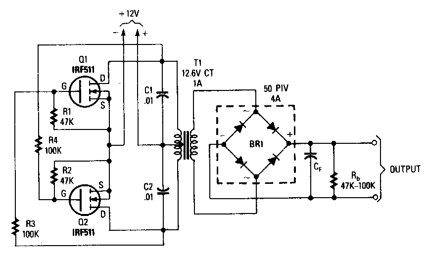
electro diagram: Power Mosfet Inverter Circuit Diagram
